Tobzorz
-
Posts
15 -
Joined
-
Last visited
-
Days Won
2
Tobzorz's Achievements
")


-
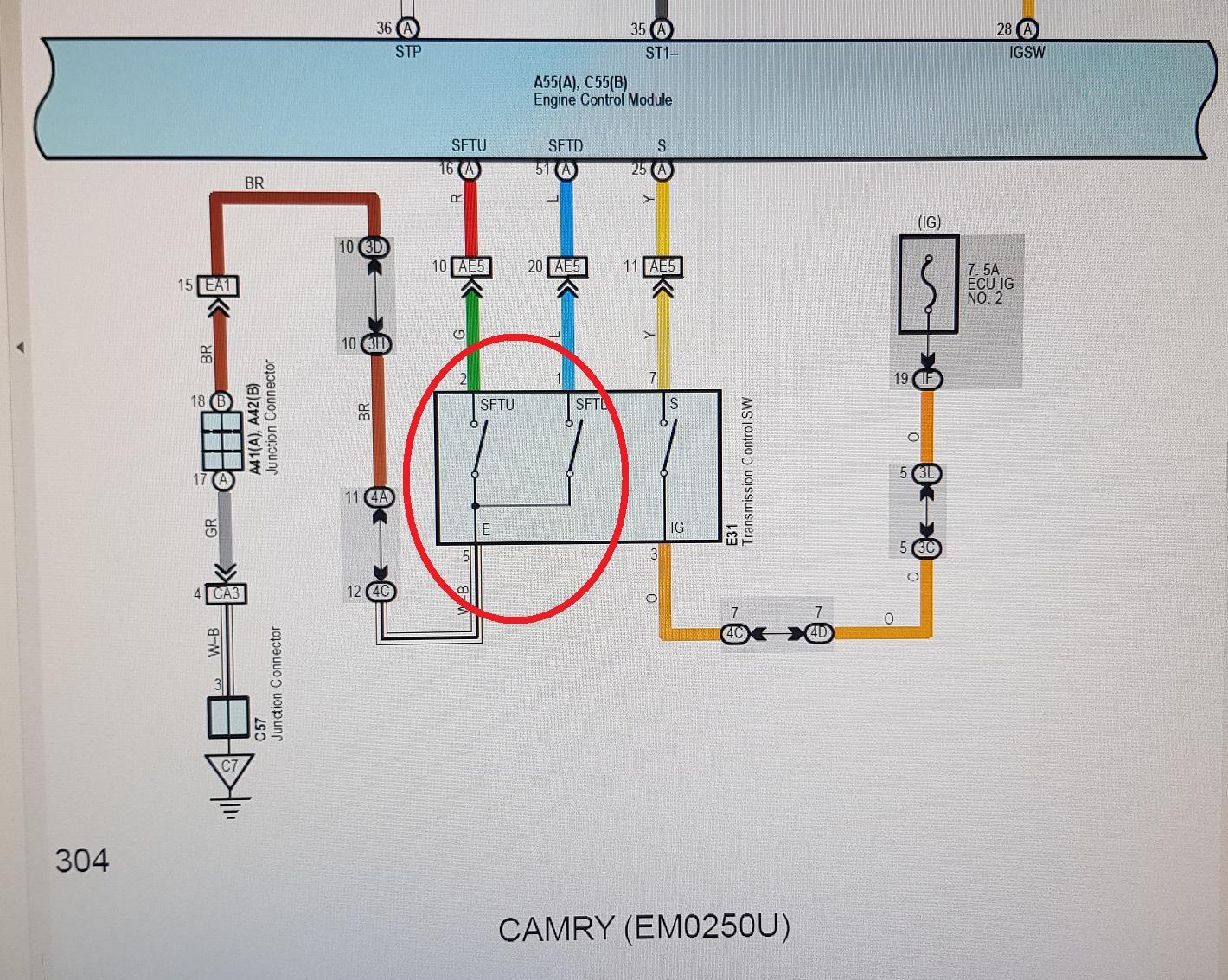
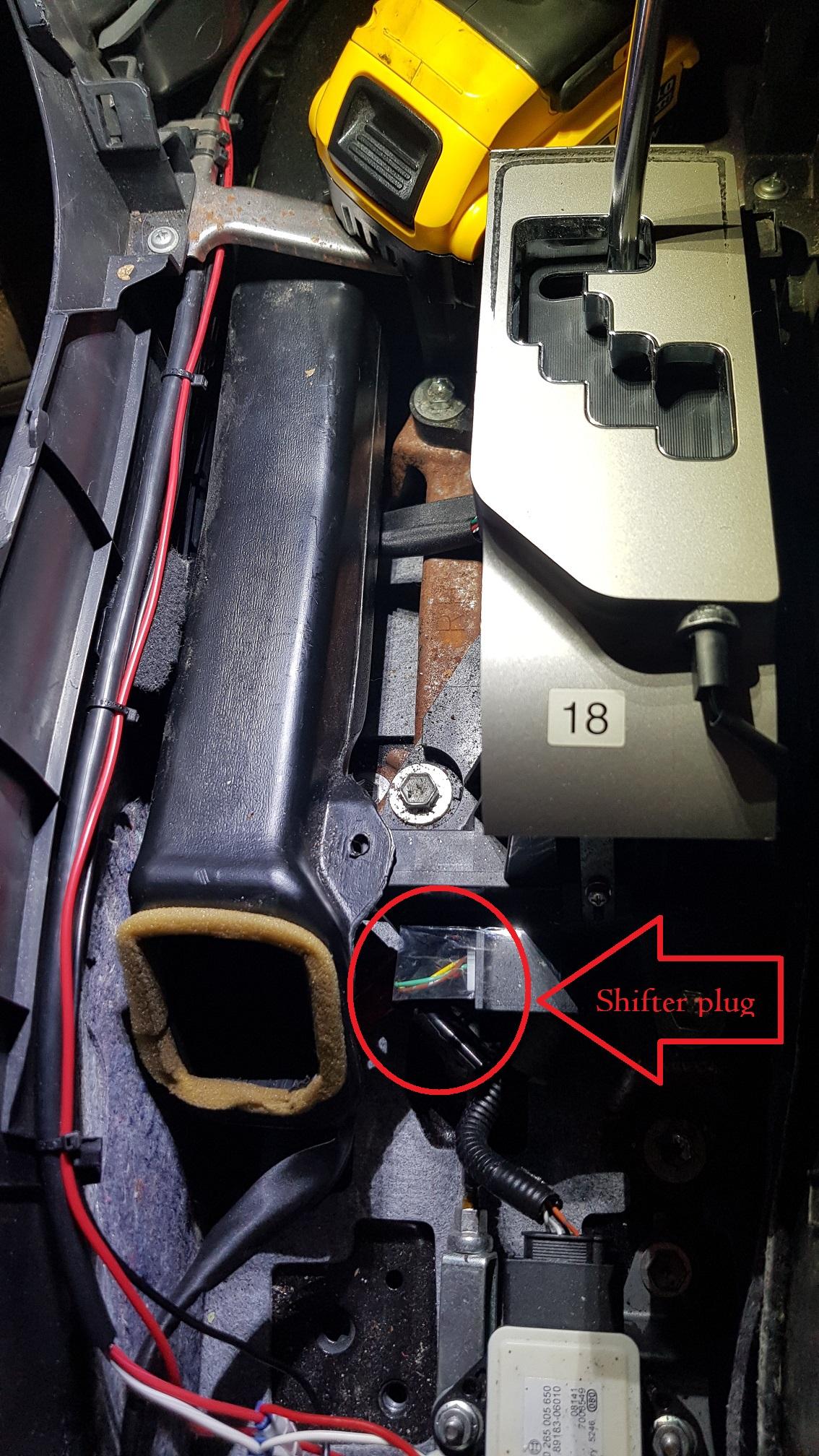
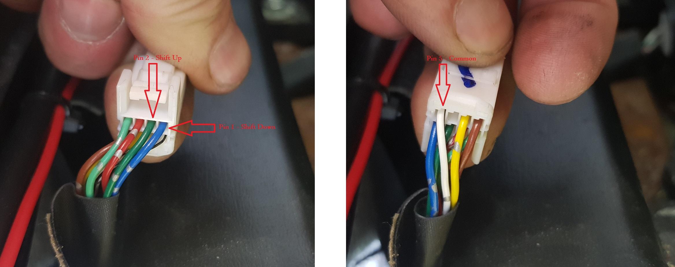
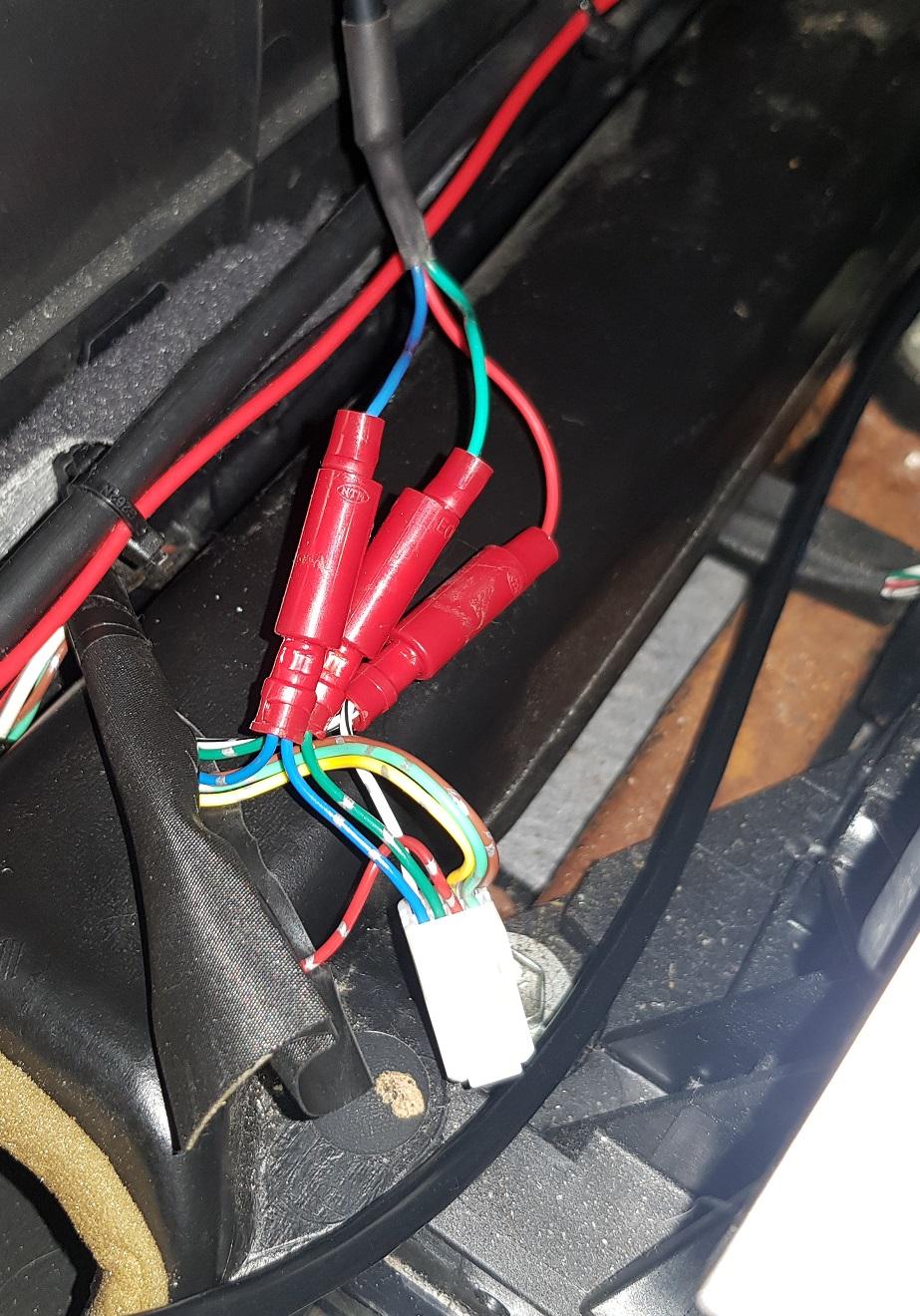
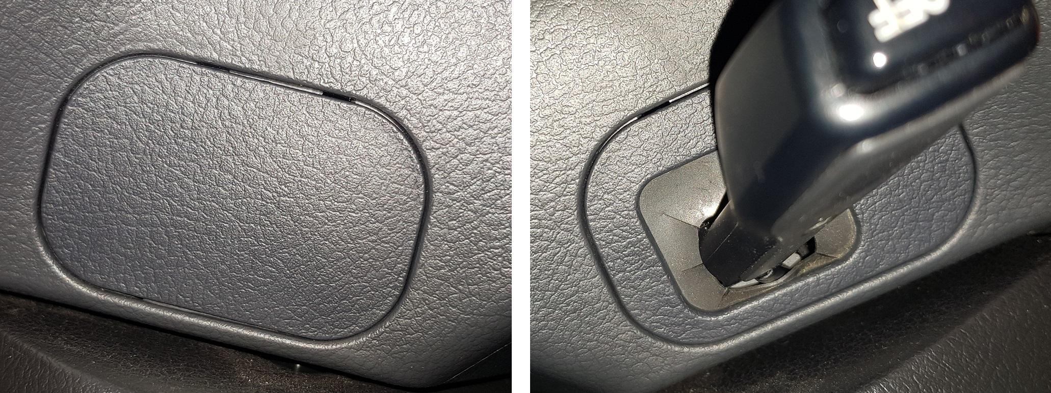
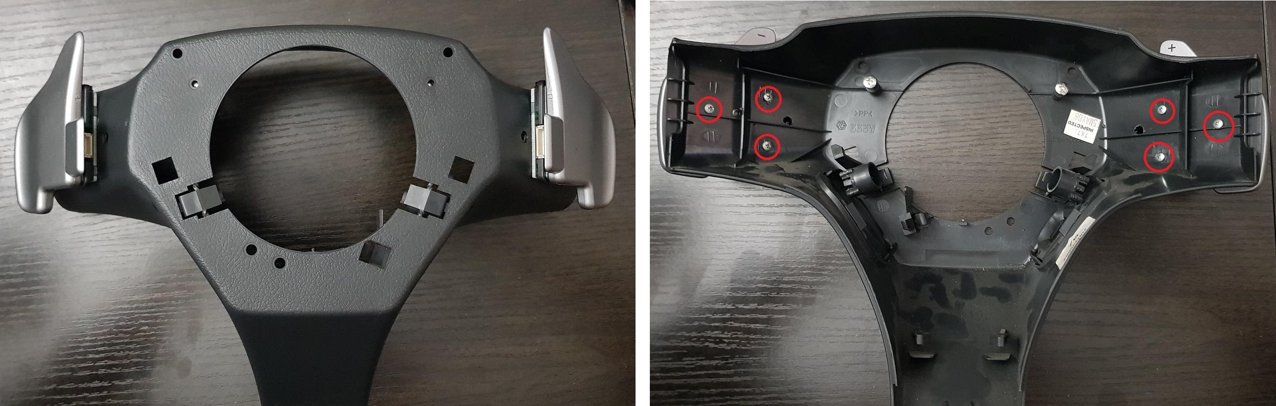
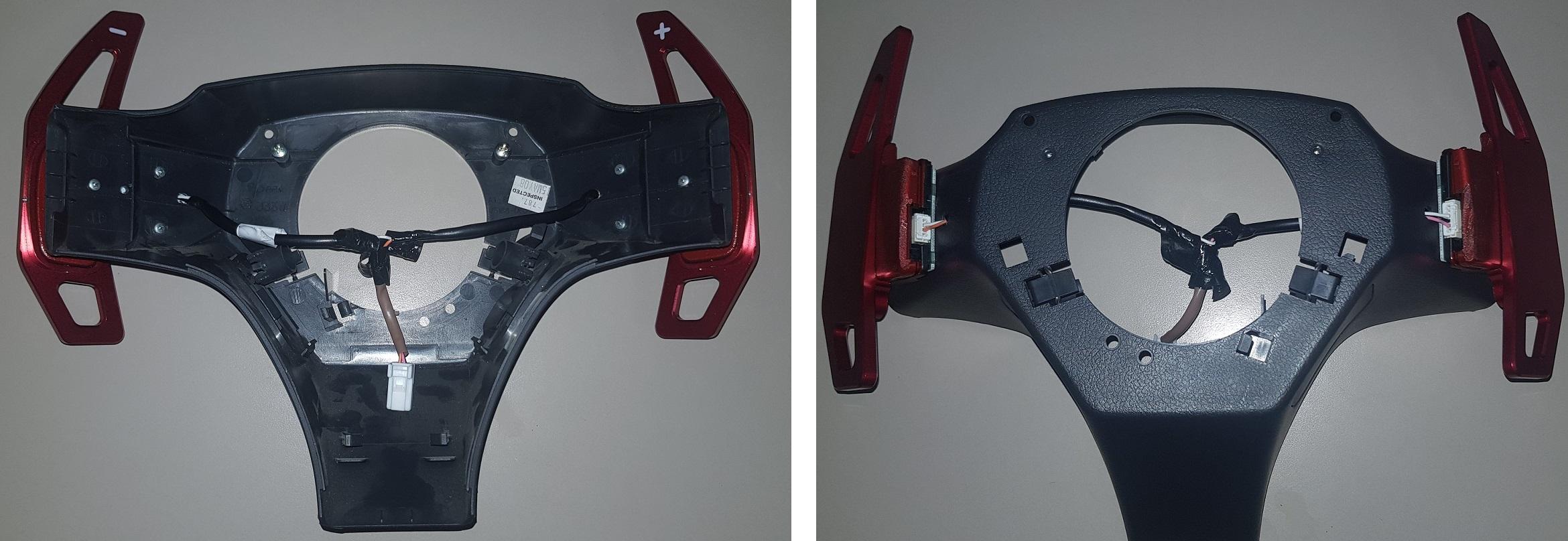
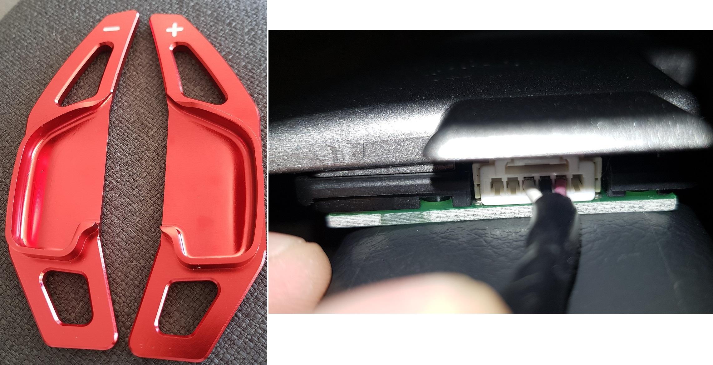
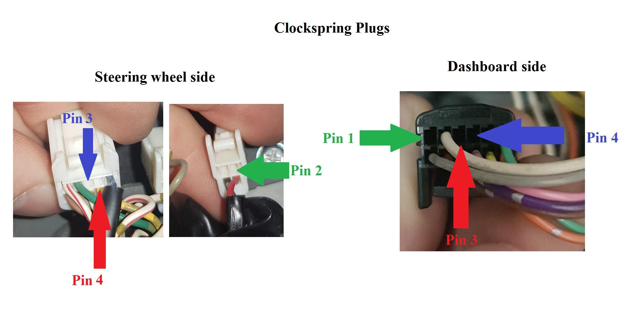
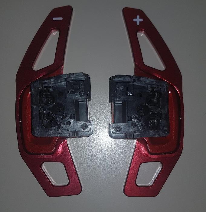
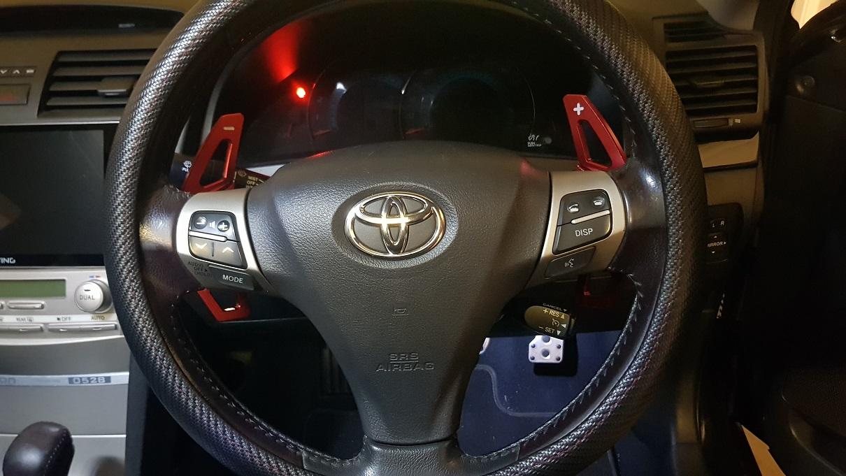
Before I start, I DO NOT take any responsibility for any damage you might cause to your car. If you’re careful and you double check everything, you should be fine! I did this in a 40 series Aurion, so I honestly have no idea for 50 series and others. I’m sure it would be similar, but it would be best to find a workshop manual for your car to be certain on the wiring. All 40 series wiring should be identical, but it’s best to ALWAYS double check first. Alrighty! Let’s get started. I’ve recently installed paddle shifters in my 08 TRD Aurion and I know some people are interested in doing this too, so I’ll try my best to explain and show how it was done. I took photos whenever I remembered, so hopefully it’ll be good enough! I started out with buying a 50 series Sportivo steering wheel, with the stock paddles attached. Originally, I was going to just do a whole steering wheel swap over, though the plugs on the clockspring didn’t match up with the 40 series, so I decided to just remove the paddle shifters. They only consist of 3 wires.. Shift up, Shift down, and a common wire. If you have a Multimeter of some sort, then it’s best to check continuity on the paddles between Shift up and common, and then Shift down and the common, just to be 100% sure you’re using the correct wires and you’re not going to create a short circuit when you pull the paddle. It was also useful to have the whole steering wheel with pins that I didn’t need so I was able to use them on the clockspring plugs for the wiring I added. Otherwise you may have to track some down from a wrecker or look online to buy the pins. The first step was to disconnect the battery so I was sure not to short out anything. Then I removed the centre console and found the plug at the rear of the gear shifter. There is a white 8 pin plug located at the rear, fairly easy to access. After looking through the Aurion workshop manual, I eventually found the wiring diagram of the pin layout for the plug. I believe that the same wiring can be accessed under the dash somewhere, though I wasn’t sure where it was and found it easiest at the plug under the centre console. Pin 1 – Shift Down (Blue with silver stripes) Pin 2 – Shift Up (Dark green with silver stripes) Pin 5 – Common (White with Black line) With the battery still disconnected, I cut each wire and then crimped them back together using a female bullet lug (this also gave me a good spot to test for continuity between the wires, along with giving me somewhere easy to plug in the wiring I needed to add for the paddles). I then plugged the shifter plug back into the back of the shifter and used my Multimeter to check for continuity between Pin 1 & 5 when the shifter was pulled Down in ‘S’ Mode, and then between Pin 2 & 5 when the shifter was pushed up in ‘S’ Mode. I then crimped on some male bullet lugs onto a 3 core cable (it doesn’t really matter what cable you use.. Just make sure you remember which core is which!), plugged them into the female bullet lugs and then ran the cable through the back of the centre console and up underneath the steering wheel. Using some of the spare pins on the steering wheel I had bought, I soldered these onto the cable I had ran to the steering wheel. At this point I taped up each core individually and just left them under the dash for a bit and moved onto preparing the steering wheel. Steering wheel removal: PLEASE BE SURE YOU HAVE SOMEWHAT OF AN IDEA ON HOW TO REMOVE THE STEERING WHEEL! PLAYING WITH AN AIRBAG CAN ALWAYS BE A BIT DANGEROUS. BE SURE TO LEAVE YOUR BATTERY DISCONNECTED FOR AT LEAST 15 MINUTES BEFORE REMOVING FOR SAFE MEASURE. Underneath the steering wheel on either side, are little plastic covers. Remove these to show a Torx screw head (size T-30 I believe). They probably won’t completely come out as they’re locked in the steering wheel plastic. Though once they’re undone, the airbag should just pull out. Carefully remove the 2 plugs by pulling up the yellow tabs with a small flat head screwdriver. Before completely removing the steering wheel, REMEMBER the position of it! You definitely don’t want to put it back on in the wrong spot. The centre bolt is a 19mm if I remember correctly. LOOSEN IT BUT DO NOT COMPLETELY REMOVE IT JUST YET. Pulling the steering wheel free from the shaft can be fairly tough.. But it’ll eventually come free after a lot of yanking at it and you’ll be happy you didn’t completely remove the 19mm nut as the steering wheel will most likely come off with a lot of force. Once it’s loose you’re free to remove the 19mm nut, unplug all the plugs and feed them through the back of the steering wheel. At this point I removed the plastic backing of the steering wheel and then put it back on the car so I was able to still drive it while I waited for the paddle extensions to arrive and also give me time to modify and paint the paddle shifters. Probably took about 2 weeks to have it how I wanted it as I really only had the weekends. So once I had the plastic cover off, I just made the shifters sit as flat as I could to avoid them hitting any of the stalks (Headlights, wipers, cruise control). It really depends what paddle shifters you try to use.. Though to attach 50 series paddles, I removed one side of the plastic cover that holds the printed circuit board for the shifters, drilled small holes through the steering wheel cover, and then just used the existing screws that held the PCB cover together, to mount them onto the steering wheel cover (I think that all makes sense..). I also drilled holes to feed the wiring inside the cover. It might look a little dodgy, but once it's all back together you can't see anything. Once I had the paddles cut down, painted, and attached to the extensions, I had to once again remove the steering wheel. This time around I had to remove the clockspring from behind the steering wheel. I didn’t get any photo’s at all of this, though there’s just a few little plastic clips holding it in place. I’m sure there are some videos or other forums out there that have a more detailed explanation on how to remove it. Be careful not to go spinning the clockspring around as it only has limited amount of turns in either direction as there’s a ribbon cable inside. On the steering wheel side of the clockspring there are 2 plugs, a white 10 pin plug and a white 4 pin plug. On the dash side of the clockspring there is a black 12 pin plug. In the dodgy photo I’ve made up, you can see what pins I found that had continuity through the clockspring.. Pin 3 from the steering wheel side matched up with Pin 4 on the dash side. Pin 4 from the steering wheel side matched up with Pin 3 on the dash side. Pin 2 on the smaller plug matched up with Pin 1 on the dash side. You can decide which pin order you'll use as it really doesn't matter. You just need to have Shift up, Shift down, and the common wire matching up on either side. I’m sure it’s not going to change from car to car.. But PLEASE double check this with a Multimeter just so you’re 100% sure it’s going to match up. Remember that this is all on the clockspring, the photos just show the plugs, I just didn’t take any photos of the actual clockspring. Once I was confident with all this, I put the clockspring back in the car, attached the steering wheel plastic cover back onto the steering wheel, plugged the wires from the paddle shifters into the spare pins shown in the photo above and then plugged the 3 cores from the dash side that were ran up from the shifter which I mentioned earlier, into the spare plugs on the 12 pin black plug. BE SURE THAT YOU’RE CONNECTING THE CORRECT WIRES ON EITHER SIDE! Then from there it was just plugging everything back in, bolting the steering wheel on, plugging the airbag in and tightening up the screws to hold it on, reconnecting the battery.. And I think that’s pretty much it! Now you should have working paddle shifters! Overall it wasn’t too difficult, it just took a bit of time working things out and setting it out the way I wanted it. If you’re going to give this a go, just take your time and take a bit of care! I apologize if I'm a bit slow to reply, but I'll try to answer all questions if there are any. Goodluck!

-
Custom Aurion Headlights 09
Tobzorz replied to Defyant's topic in Buy & Sell - Parts and Accessories
Loving the look of them! Are these still available? If so, what is the location for pick up? -
Yep! I removed all my trims not too long ago and all the door trims have screws holding them on, so the door panels need to be removed.
-
Oh, also.. I feel I may have blown a fuse for the sequential today when fiddling around with it.. Haha. Any idea where the fuse for it might be located? I'm certain I checked every fuse under the passenger kick and in the bonnet and couldn't find any blown fuses. I've checked the manual but couldn't find anything.. Just thought you may have come across it while you were wiring yours.
-
No problem, Trent. I'll try to take some decent photos. I've been pretty busy lately so haven't been able to attempt the steering wheel swap over, though I had some time to look at it today. After searching around for a bit under the centre console, I found the plug which controls the 'S' mode, but honestly had no idea as to which colour may have been connected to 'Shift up' and 'Shift down'. Can you remember at all as to which colour wires controlled the shift up and down on your car? If I'm lucky, it might be the same on my car!
-
Alright, thanks! Another question though, sorry.. So I've temporarily hooked up the new steering wheel controls to make sure they'll work properly, and they do! Except for the 'Disp' button. I've wired it to the same as the GSV40R plug but no buttons seem to control the 'Disp'. What did you do to get around this when you put in the Master Blade wheel?
-
More so just the amount wires coming from the paddle shifts themselves. There are 3 wires which go into the clockspring from the steering wheel side. So I know one wire goes to 'Shift Up' and one goes to 'Shift down' but just wasn't sure if the third wire needed to be run somewhere. I might give it a go today and will give an update later on!
-
So, I've been taking the pins out of the GSV50R plug to put into the GSV40R plug. After taking them all out, I've noticed that my paddle shifts have 3 wires, a black, pink and orange wire. Any idea what the extra wire may be needed for? Just unsure where to run it to.
-
Awesome, thanks very much for your help. I'll get back to it all and will give another update soon on how I go! :)
-
Haha. Yeah, sorry for my messy explanations.. Still getting my head wrapped around it all :P Anyway, I'm starting to think the same thing.. I can't imagine I'd ever really use the extra features, and I rarely use my phone with hands free to make it worth my while for the pick up/hang up button. Going with the use of the GSV40R plug will probably be a hell of a lot easier and less stuffing around. When running the extra wires for the paddles, what kind of lug/termination did you use on the wire to allow it to plug into the spare ports in the connector for the clockspring? The smallest type of termination I can think of would be a bootlace. Not sure if it'll be small enough though.
-
Yeah, the photo I put up was of the GSV50R clockspring. The connection to the GSV50R has a 14 pin connector from the car side, but a 12 pin connector from the steering wheel side. I was going to keep the GSV40R clockspring and just take the connection from the GSV40R wheel and put it on the GSV50R wheel, but then I thought it might be nice to be able to use the extra steering wheel features, rather than just have dead buttons on there. So I figured if I used the GSV50R clockspring and just change the 12 pin connection to a 14 pin connection, then I'd be able to run wires to my head unit to use the extra buttons. Only trouble is, I'm not sure if anywhere will be selling the 14 pin connection anywhere.. Worst case scenario, I'll just use the paddles, and leave a few unusable buttons on the wheel.
-
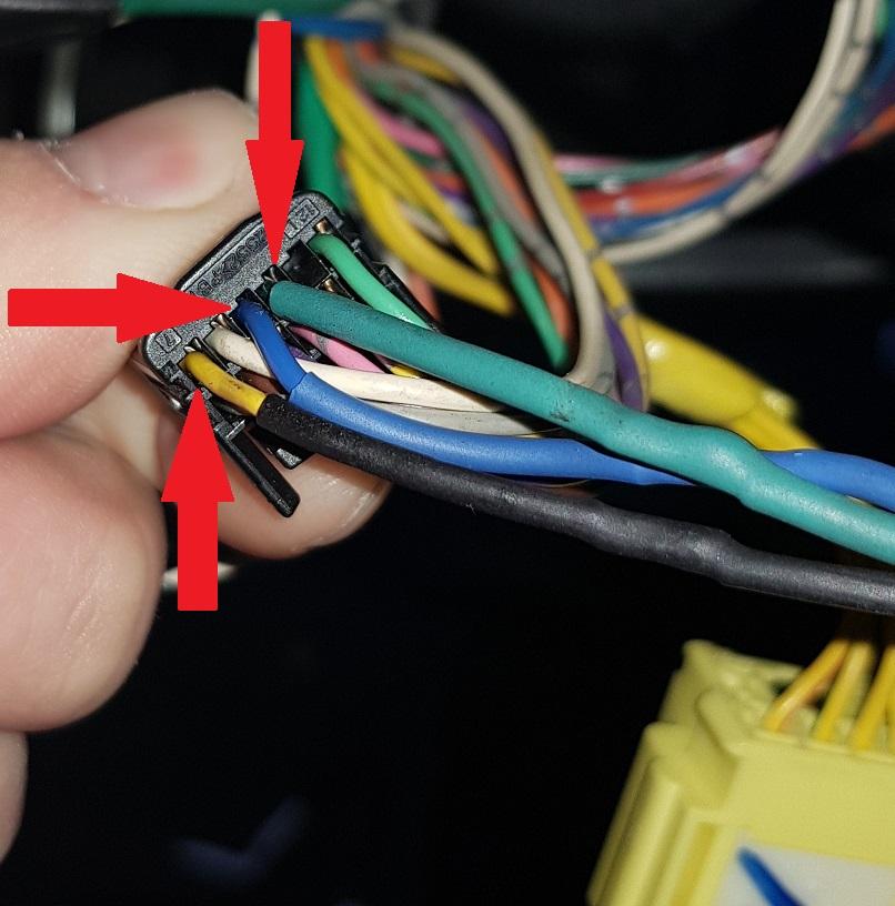
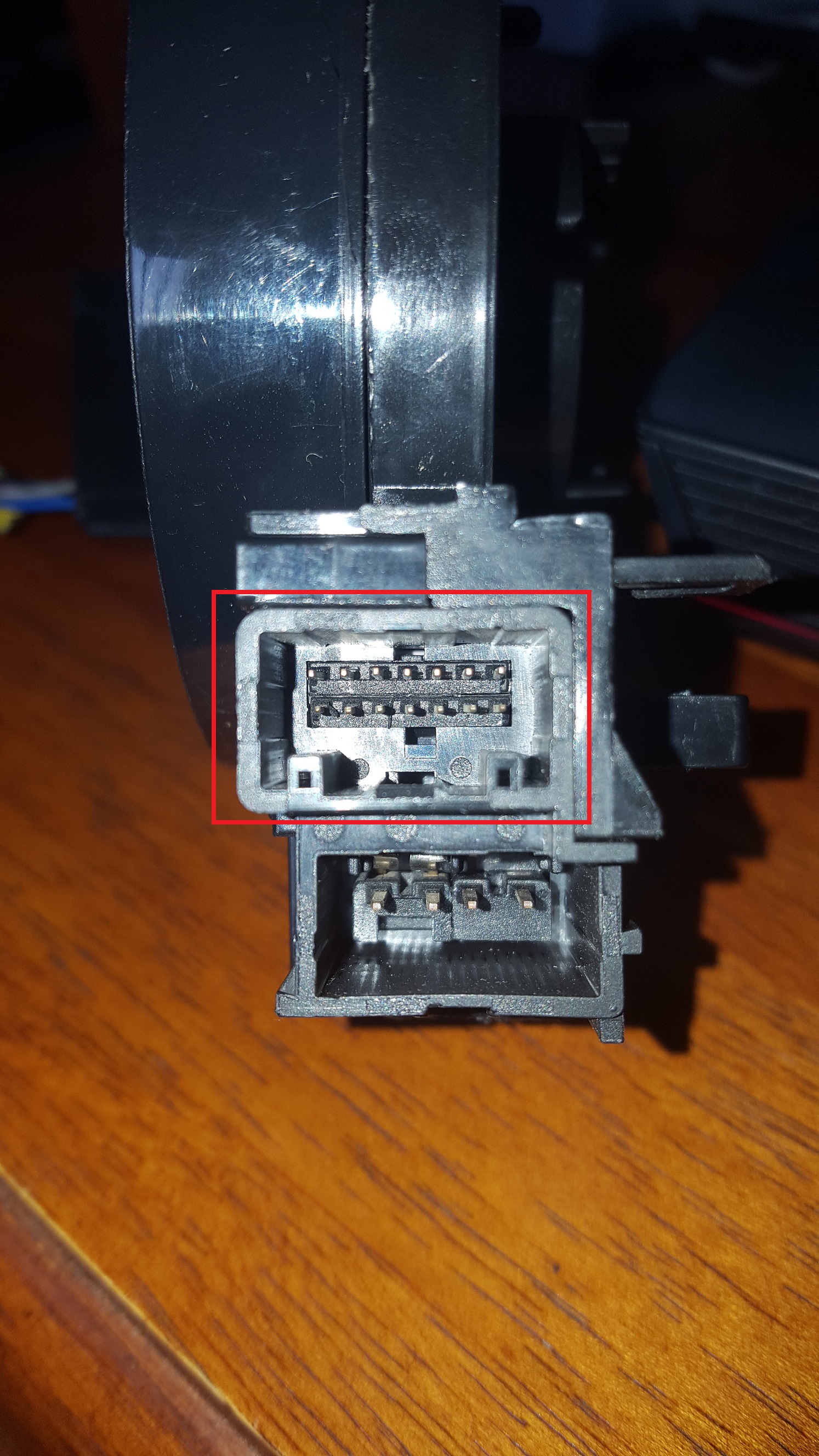
Right. Just a minor update to this project. I've bought and received the steering wheel for the GSV50R. After taking off the steering wheel from my Aurion GSV40R, I've discovered that the plug connecting to the clock spring from the steering wheel is actually a different size to the original (It has 2 rows of 6 pins, where as my GSV40R has 2 rows of 5 pins). I decided to buy a clock spring to suit a GSV50R and see how I go from there, only to discover that the connection between the clock spring and the car itself is now different! Originally I was then thinking of taking the plug (between the steering wheel and clockspring) off the GSV40R and putting it on the GSV50R wheel, but if I were to do that, then I wouldn't have the option of adding in the extra steering wheel features (Call pick up, hang up, etc, as it has less extra wires available) later down the track. So now I'm going with trying the change the plug (between the car and clockspring) so I am able to use the GSV50R clockspring, that way I can add in the extra buttons later if I decide to. This is where I need some helpful information! I've had a look online to try and find the right connection, but just can't find anything. One way is to just run wires individually to each pin, but it seems a bit dodgy.. plus I wouldn't want to cause any shorts between the wires. If anyone has any helpful ideas then PLEASE let me know! :) The connection I'm after is boxed in red below ;)
-
Yeah, fair enough. Well I've actually bought a GSV50R steering wheel already and am waiting for it to arrive. I've also found a site which sells the airbags separately but plan to wait so I can be sure the steering wheel and all the wiring will be able to connect up properly. I'll take some photos once I get started and post them up here in case anyone else is interested in doing the same thing.
-
One more thing, sorry. Can you remember from the previous post you were referring to, if the airbag is a different size to the GSV40R model?
-
Awesome, thanks very much for your quick reply. I've checked out a few other's mods on the steering wheel (including yours!) but was hoping I'd be able to use a GSV50R model as it'll be cheaper and easier to get than the Lexus IS350, and haven't been able to find any Blade Master wheels. Love all your mods by the way. Been following them closely!