shane_85
-
Posts
14 -
Joined
-
Last visited
-
Days Won
1
Recent Profile Visitors
4,721 profile views


shane_85's Achievements
")


-
Ill see if i can remember all your questions.... I have all the appropriate gear to do the programming of the atmel; hadnt thought about updates too much but if it was absoloutely required the board would easily fit into a standard envelope. The way in which i have approached this project is to not modify the car looms at all and to just "hang off" of the existing wiring. You could use the mode button but you would need to modify the wiring (to stop it changing the mode when you pressed it); the channel up and down buttons are the only two that do not have effect on the head unit when in AUX mode. The standard usb cables do not connect to the serial pins, i have actually found it quite difficult to find accessories which have a plug that supports serial and went through a few before i found a suitable one - Radix supplies new ipod plugs but havent bothered ordering any from then yet. If any of you guys wanted to try this project yourself and build the board etc etc im happy to give more detail with what i have done for wiring etc and also happy to program an atmel and send it out to you at no cost above the purchase price of the chip. Not sure if that answers your questions
-
Unfortunately at the stage we are unaware of where you can get the original plugs, sockets or pins. You will have to improvise as best you can with what you have, i have used pins from other connectors that i 'made' fit and others have just tinned the wire and stuffed it in the back of the plug; probably both equally dodgy but both effective. So long story short, connect the pins with the resistor as best you can as there is no easy way of doing this.
-
You are correct in saying that the generic wiper blades will not fit, however, this design is not unique to toyota and from what i understand, its not all about trying to ruin DIY work for us..... but on the plus side, you arent stuck with using genuine blades!! The type of wiper blade on the Aurion is relatively new to the market (in contrast to the generic ones which have been around for many many years) but has been creeping into the market for quite some time now and there are many other cars that run these, and have been doing so for quite a while. This type of blade is referred to as a japanese style blade. If you remove your wiper blade from the original assembly you will notice that the two metal rails that fit into the rubber insert are both curved. The reason for this is that it is supposed to give you more consistent pressure along the length of the blade; in contrast to the orignial blades which apply additional pressure only at the claws of the arm to the blade (not sure if i explained that clearly but thats how the tridon rep pitched it to me last year - im an ex supercheap auto manager) Long story short the new type of blade/wiper setup is supposed to give better performance and lifespan; unfortunately at a slight inconvenience to us consumers as it has changed a standard that has been around for years. So what you need to do is slip into a retailer which sells an updated range of wiper blades; as an ex manager (thats right, an EX manager so im not trying to plug for them!) i know that any supercheap auto store stocks tridon which include what you need in their range. MRJ2028-2 ..... Take that part number into SCA and say i want these, chances are if you ask for blades for an aurion and get some little punk serve you, you will end up with the wrong ones in the form of generic blades. This is the part number for the correct wiper REFILLS made by tridon and from MEMORY(dont quote me) will set you back around $30 or so. They are a rubber blade that is coated in graphite; not the horrible squeaky (but long lasting!) silicone variant which i think you would struggle to find in this style. I have had them on my aurion for bout 3 months and they work great. Not sure how the cost of these competes with toyota because it was way too convenient to just pick them up from work when i worked at SCA. P.S DJKOR i saw you at my taringa store late last year but by the time i realised it was you (i recognised your car) you were reversing out so i missed trying to talk your ear off - Bit of useless info for ya to show what a small world we live in. Hope this helps!!
-
I have had my eye on this site for a while seem to have a pretty good price on thier pcb's. i.e. assuming 20x20mm; for 10 without silk screening, $29.00 ($2.90ea) or 10 with silk screening, $41 ($4.10ea) which is not too bad. Silk screening would be nice but its not a must have, especially with how simple the board looks at the moment. Will do some rough calcs and take a ROUGH stab at how much it would cost us for a batch of say, 10.
-
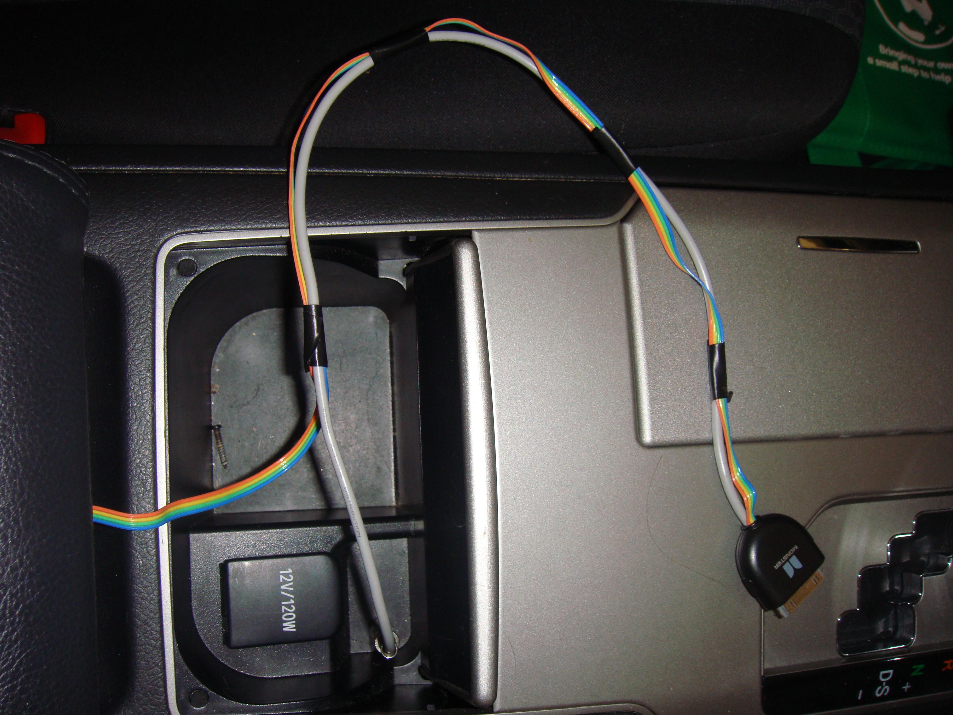
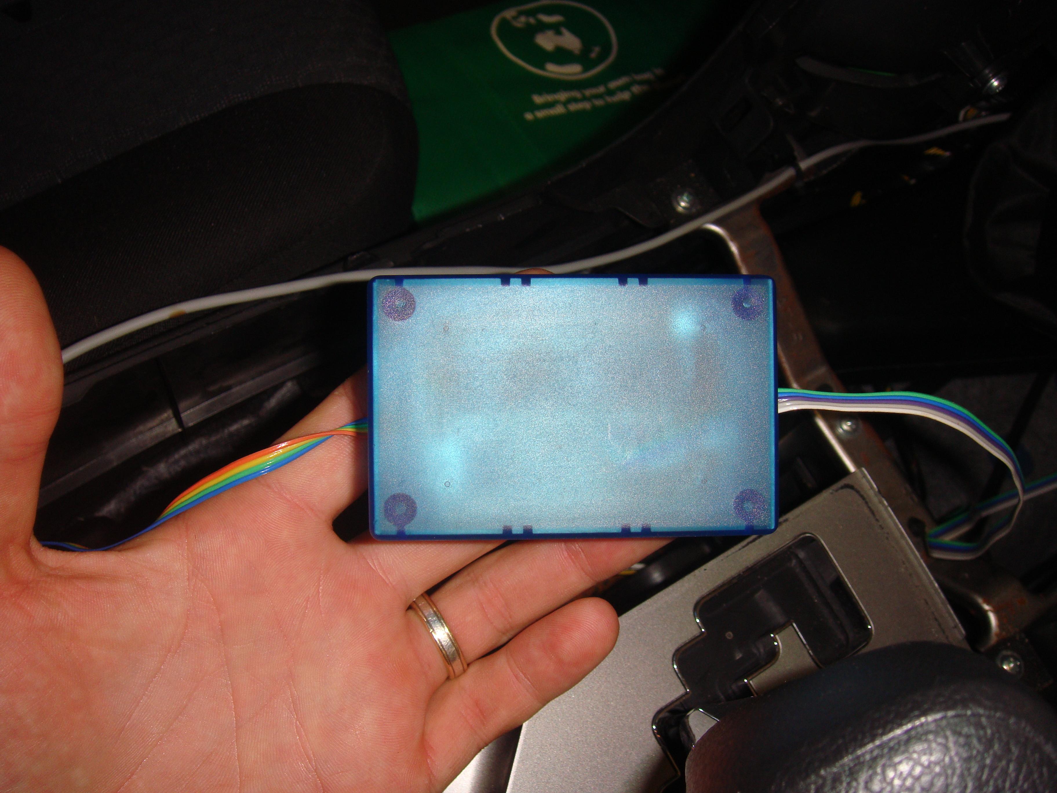
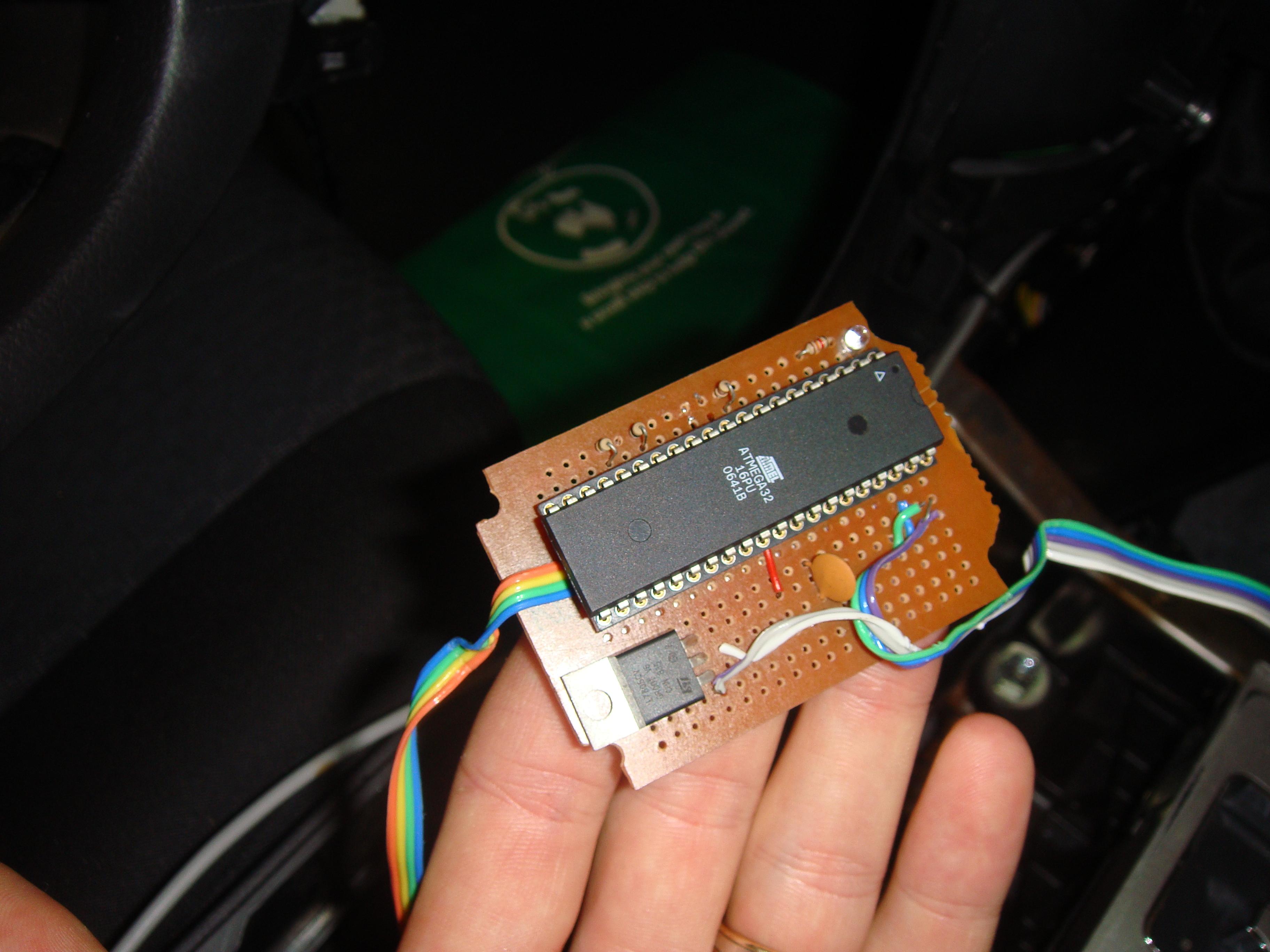
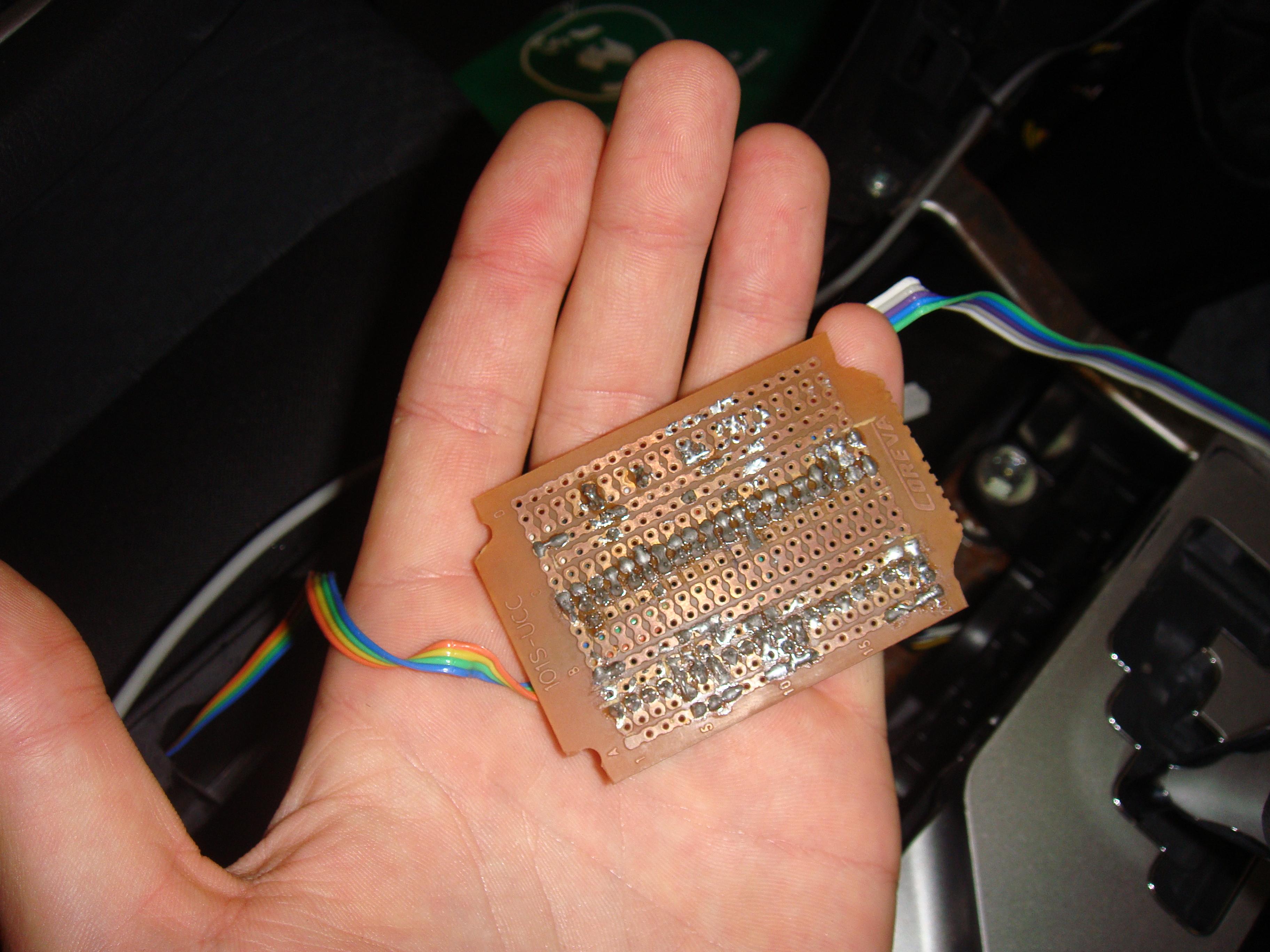
As promised in the AUX thread i started, heres the next project i have been working on.... For people out there with slightly advanced knowledge in electronics etc (and even those that dont keep reading!!!) this is a really nice addition to the AUX on your stock HU. Basically all i have done is to tap into (not modify in any way!!) the stock steering wheel controls. I have a microcontroller sitting there monitoring the line voltages and when they change id deciphers what button has been pressed depending on what the voltage drops to. To this same microcontroller i have connected the 30pin dock connector for an ipod/iphone through the serial port. Through serial communication with the ipod quite a lot is possible, check out what you can do here - for simplicity reasons i have thus far only used mode 2. So basically i can connect whatever functions i like (from the above link) up to any button press (or button press sequence) on the steering wheel!! I have a fully functioning version of this in my car at the moment and it has been in there for about 8 weeks now with no probs so far. I have tested it with an iphone 3gs, ipod nano 3rg gen and an ipod classic 6th gen. It SHOULD work with any apple ipod/iphone which uses the above protocol. the functionality i have given my unit so far is to switch on the ipod/iphone and begin playing when the unit is plugged in (with the car on of course!) and for the track up and down buttons to work with the track up and down on the ipod . SIMPLE! The only prob i have at the moment is that i can not find the cable that i need, so unfortunately i have a control cable (in the form of ribbon cable) and a shielded cable running to the unit separately which i do not like the look of. Please keep in mind this whole thing is a prototype that i threw together in a day, it worked perfectly and i havent touched it since!! I would really like to make one of these units properly - that is get a proper pcb made up and make it out of surface mount components. I could get it down quite small (bout 20x20mm roughly) and make it look tidy (unlike my prototype!!). Before i continue, id just like to add that: im not trying to make money here, im not interested in making money from these projects and i am posting this purely because it interests me and if i can help people out in achieving the same things i have then i will be happy - my two projects thus far have certainly made my driving life much easier and more pleasurable. If in any way i am breaching rules etc of this forum let me know as i my intentions are all positive. So.. i would love to get a batch of these made up with properly manufactured PCB's and surface mount components. Would any of you guys be interested in being a part of this?? Not saying this is going to happen just wondering if its a feasible option to consider and gauging what the interest would be. Also, any ideas on what sort of functionality you would like to see in this? i love playing around with this stuff and would welcome every suggestion as to how to make this a more useful device for us all. If anyone is interested in further details (code, schematics etc) let me know.

-
Hey Guys, its great to see my original post generated so much interest!! First of all id like to apologize for my absense/ignorance, my wife and i have been very busy tending to our first son who is only a couple weeks old :) On that topic i should probably apologize in advance for my slow replies etc in the future for the same reason. Anyway, i have been following the thread every now and then and have found it very interesting with regards to the guys who can not get my original mod working. From the limited research i have done it does seem as though the GPS units etc rely more-so on the AVC-LAN protocol. I originally looked into making a device that would be able to communicate with the GPS units with the AVC-LAN protocol but it looked like a LOT of work and thats as far as i got. Ideally, you would be able to purchase an IC which converts a simple serial stream (or some other simple protocol) into the high level AVC-LAN but unfortunately these chips are pretty much impossible for consumers like ourselves to get a hold of. I have found a couple of efforts and really good starts to writing software which can emulate these chips but i did not find anything which is tried tested and ready to go. Obviously the AVC-LAN is not unique to the aurion or toyota (http://en.wikipedia.org/wiki/IEBus) and there are several other forums which mention and discuss this protocol if anybody is interested (google finds these quite easily). So to put some actual substance into my post, i did find it interesting that Steven found out that the AUX signal is still analogue with the AVC-LAN and that only the switching is done through this protocol. When i originally looked at the AVC-LAN it did seem daunting the amount of info that is thrown back and forth (and the manner in which this is done) BUT if all we need to do is tell it to switch to AUX, this may simplify the matter a fair bit. Would love to figure out a solution for you guys but at the moment i have neither the time or resources to do so - not going to rip my HU out and sit on my desk everytime i want to have a play around. That said, i have been tinkering in my absence and comepleted something else which may be of interest to people; IPOD STEERING WHEEL CONTROL I feel that this may also generate some interest so im going to start a new thread for it to keep this one clean; be sure to have a look!! Believe it or not, i got an original Monster FM transmitter with the car thanks to the dealerships dodgy cleanup job (was stuffed down between the seat and centre console). All i did with this was to replace the cable from the charger to the ipod with a shielded 4 core cable - 2 wires for the power and two for the audio (+the shield). obviously the power wires went straight back to the charger and the audio wires were terminated with a 3.5mm headphone jack to go into the AUX mod socket. Looks nice and neat but is now in a thousand pieces for one simple reason: Noise. I could not find the correctly shielded cable for this application and hence was burdened quite heavily with interference when the car was running which annoyed me to no end. For me there were three solutions i could have used to get around this: 1) Find correctly shielded cable with the configuration i needed - close to impossible for small amounts at a low price 2) Install a noise filter on the outlet where i charge the ipod from - not ideal as not REALLY a solution to the underlying problem (incorrect cable) and $$$ 3) Deal with it/ditch the idea and charge as required - This is what i opted for and started on my next project. For a little while i just left the charger unplugged and plugged it int (and yes, put up with the noise) until the ipod was charged again
-
Doesnt look good mate, as i mentioned last night, its possible that they left more than just the plug out of the head unit..... From what i can see of your picture, there are tracks running from the pads where the plug should be to blank surface mount pads for additional components. I could be wrong but thats what i can gather from your pics. I think that they have well and truly made sure that you are not able to use AUX with this HU. Short of actually dismantling completely and checking out where things go you will not know for sure but i guess in hindsight, the fact that they have not even connected the plug is probably a fairly good indication that they have gone to the effort of leaving other components out, prob not really a lot you can do in this case. In saying that i guess i started with a remotely similar issue with the AUX in the first place and found a work around for it, might be worth pestering fujitsu for a reply. I would love to be proven wrong here but i think you have just confirmed that the GPS units will not work with this mod :( I guess you could always see if there is ANY activity on the connections you have made (resistance, voltage etc) but realistically even if there is activity its not an accurate indication either way... Probably just beating a dead horse so to speak
-
Bugger! Thats not what we all wanted to hear! Look forward to seeing the pics tho. Didnt hear anything back from fujitsu?
-
There aren't even any blank pads on the PCB? Top suggestion i would say. Even if there is no plug there should at LEAST be some pads on the PCB. It is common practice to have a generic PCB that will or will not perform certain functions depending on the model you get - The pads and tracks are still there, just not connected (Have a look at the motherboard on your PC!) The other question though is how much other stuff have they left out of the unit if they have decided to ditch one plug? Im assuming if they went to the effort of ditching a plug (presumably for cost saving) that they would NOT bother developing/changing the PCB to exclude it completely? If it does have pads on the PCB where the F14 plug should be, you would have nothing to lose by trying to solder to those pads - just make sure you stick with the 1k resistor rule for poking around. Where you have originally soldered the wires has a very small chance of working i would say. Your unit does resemble the pictures in the manual for navigation MINUS the plug for AUX (and the one next to F9). This could well be an indication that as well as leaving the pins in the plug blank they have ditched the entire plug assembly for the plugs with no wires in them at all. Going by the manual for navigation, the connections that you have made (presumably this is plug F10) serve no purpose (that is noted in the manual) for this unit, i.e. are not connected to anything. this of course lines up with what you said... that it did nothing. I assume it did not do anything else out of the ordinary with the connection of these plugs? I would have my money on checking out where the F14 plug SHOULD be on the PCB and not on getting anything useful from fujitsu ten. I doubt very much that they will give you the information you have requested, you never know tho. On the same note, if you did get something, chances are it would be something generic (as per the toyota manuals) OR a schematic which will be of no use if you have no orientation on which plug is which, especially if it doesnt exist. Hope you get this sorted out, there has to be a way around it. Dont give up on this yet, im sure there are many people with the nav units anxiously awaiting for you to find the work around! Ill keep my fingers crossed for you!
-
Ditto here, good work DJKOR :) You do raise an interesting point about connecting to the shielded ground instead of chassis ground. The thought didnt even cross my mind that it should be connected to shielded ground, once again i ASSUMED that the shield is for shielding purposes only - end of story. I didnt look quite as deep as you did though with the schematic you dug up. The part of the manual i referred to used the chassis ground as the reference for testing the AUXI terminal and i assumed thats what it should be connected to. I guess in essence the chassis and signal ground must be connected somewhere and a chassis ground is much easier to find than the shielded ground for testing purposes. This does raise an interesting point about how you mentioned about not being able to select AUX if nothing is connected to it. As you say, obviously they use the signal ground in the jack so it would be relatively simple for somebody to incorporate this into the mod if they wanted this additional functionality :) Good work mate, pitty ive already said i guessed/assumed with the resistor cuz i could have said i was "replicating what the genuine AUX has" :P -Shane
-
It was this comment that provoked my question rather than answered it. The specification referred too expects to see a voltage of below 1V to recognize it as "low". Assuming the pull up resistor in the unit is a 1k2, the 1k resistor put the voltage at the pin way above 1V. If my assumptions are correct this means that the 1k resistor might work in some conditions/cars and not others depending on the tolerance stack up. You will also not have enough current for the connector to be reliable in the long term from what I can see of the connector system. I couldn’t see if the terminal was gold plated (required for very low currents). I asked the question because I am interested to either learn something new or raise a fault finding pointer if it doesn't work. Without seeing the HU internal circuit I don't think I would want to say don't fit a resistor...! Hey guys, glad to see my post has been useful! :D So to get to my point as to why i said to put the resistor on there.... Simply put, this is obviously not a toyota endorsed modification, and who knows what the factory harness has in it, it may just be a wire as you say(maybe somebody could clarify this?). I felt that it would better to be safe than sorry when i was doing the mod myself, and after doing the mod it worked with absolutely no worries at all, and best of all, NO SMOKE. That said, what happens when you short it out directly?? i dont know and i dont intend on finding out...may be fine may not be. So to summarize, i said to add the resistor because im unsure if it will cause any damage without it, and i would feel HORRIBLE if i were to say "yeh it will be fine to not add the resistor" and then for you guys following this mod to see smoke and dollar signs for a new HU. Ive just posted what i did for you guys EXACTLY as i did it because i know that it works :) I have done about 800km of driving the last few days and had no probs at all with the AUX which has been awesome. Just a semi-technical aside as to why i used the resistor in the first place. Feel free to correct me, draw ur own conclusions etc etc but this was my train of thought for what its worth. Having spent many years at uni making circuits, PCB's, dealing with Microcontrollers etc you tend to get into a few habits to cover yourself. One of these habits that I got into (not saying its how things SHOULD be done) was never tying an IO line directly to ground. Now there were a couple of reasons for me to do this (and bad experiences was among them). I wont bore you with the detail but basically an IC trying to drive an IO high when it is directly grounded = bad. But the line on the head unit is an input right? correct, but my habits have prevailed!! On the same token though, it is good practice to tie unused IO lines to ground (or VCC depending on application) to try to reduce power consumption, i always did this through a resistor as a lot of the circuitry was experimental and under development. That said, another habit you get into is to NOT going around shorting things out when you dont know what exactly you are doing (i DONT have internal schematics for the HU)... If you have to g around shorting things out, at least give the circuitry a chance to tell you something is wrong before the smoke comes out (you cant put the smoke back in !!!) . This is where the resistor came into it, as for size, educated guess. If anyone is willing to try without the resistor im sure we ALL would love to hear if you do need to go to the effort of putting it in there or not :) Thanks guys, Shane
-
beats me too, i was not exaggerating when i said it cost me round $5 for the bits (well actually bout $30 with a few extras for the toolbox ;)) but i guess they have thier reasons?? I test drove a couple of camry's and i swear i saw AUX in at least one of them... I guess we will just have to put it down as an "oversight" as they were concentrating on building an otherwise brilliant car :) (would have been better with AUX tho...)
-
Its well worth the time and effort to do it i can tell you. You forget all about the convenience and clarity of an AUX input (compared to FM transmitters) when you dont have one. Anyway, i assume it should be somewhat the same proceedure for you except you will need to refer to this manual for your pinout (Page NS49 & NS50). It seems as though its the same deal from what i can see, except the pins have different names. The other prob you may run into is that it seems that the AUX has its own plug on the back of your unit so rather than exclude just wires you may be minus an entire plug?? Perseverance and creativity will make short work of that tho :) No harm in having a look i suppose, i was really surprised at how easily the HU came out actually. So im ASSUMING (i know its bad to assume but it paid off for me!) from the manual you will be looking at F14-6(ADPG) to F9-20(GND) - enable the AUX ....through 1K resistor that is F14-2(VAR+) - Right Signal, F14-3(VAL+) - Left Signal & F14-5(VA-) - Signal Ground/Shield Best of luck and let me know how you go :)
-
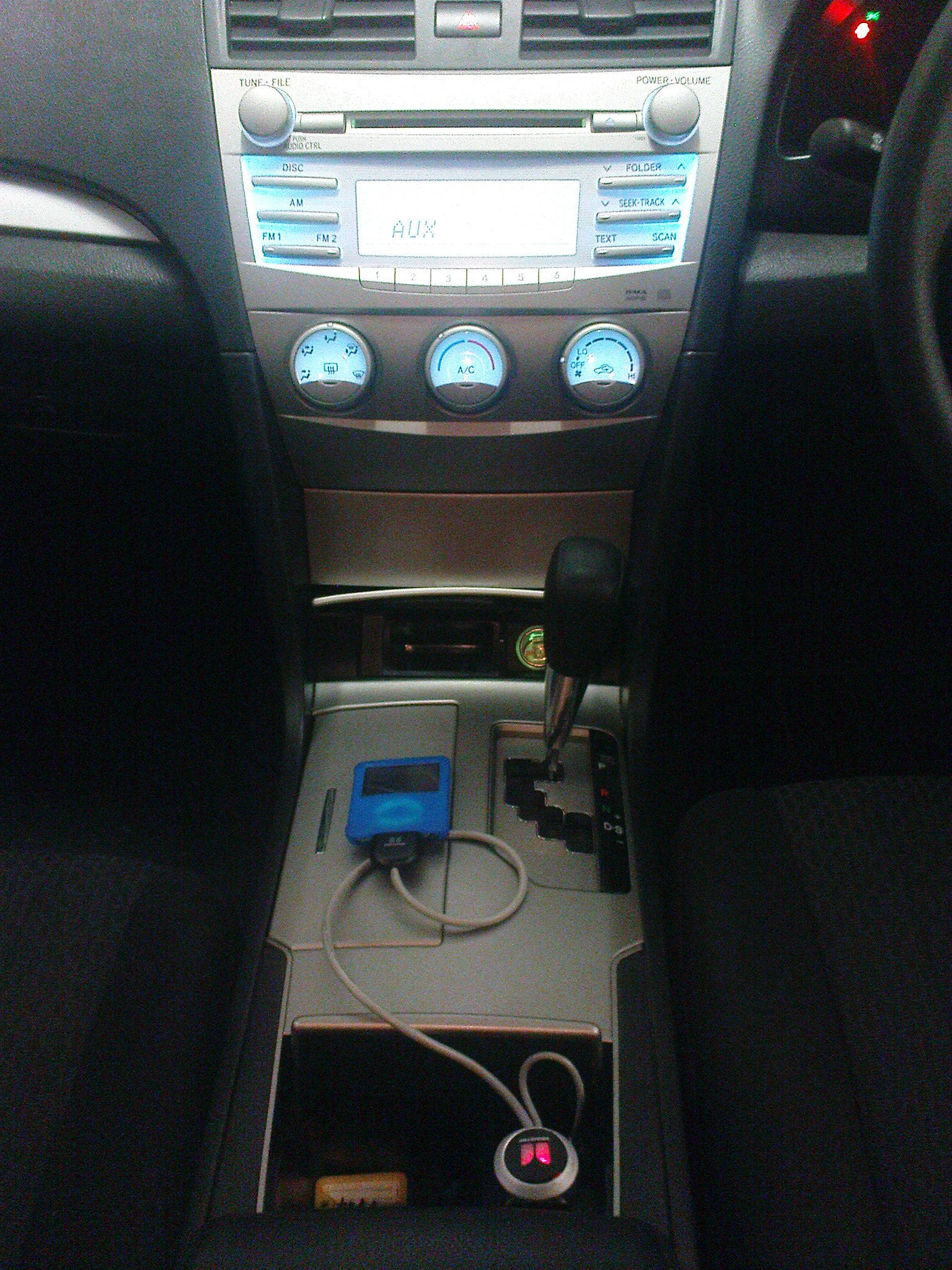
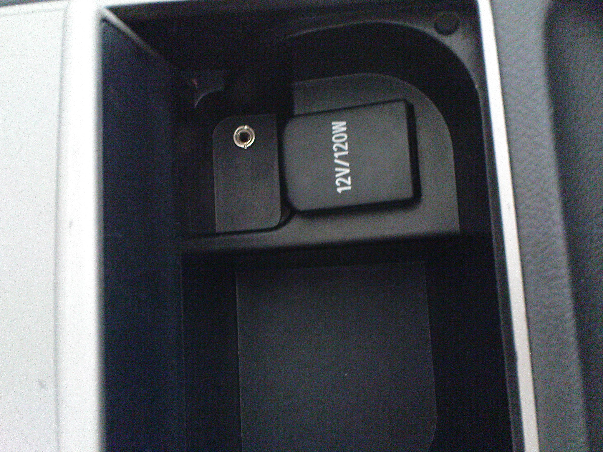
NOTE from DJKOR: Due to the constant stream of questions regarding this modification both on and off the forum, I will no longer be answering any questions about this modification regardless of the question content. ----------------------------------------------------------------------------------------------------------- Hey guys, this is my first post so ill try to make it useful as possible. Ive been trawling through this site for a while getting some ideas and heres the first one that has eventuated. It seems that the factory CD/MP3 player on the aurions (and probably the camry's) have provisions for AUX input and that toyota has been too cheap to bothger utilizing it. All they needed to fork out was a few dollars for some shielded cable, ONE resistor and a headphone jack. Anyway, down to the point. If you pick up where toyota decided to not leave from, this is what you need to do to get AUX input. (Please refer to the Audio_Visual section of the manual avaliable here). - Refer to page AV-16 to AV-19. P.S mine is the "Standard Model" 1) Connect F8-19(AUXI) to F6-7(GND) through a 1K resistor, DO NOT GROUND DIRECTLY -> AUX will not work if you do this and the original AUX module DOES have an internal resistor (Thanks DJKOR) 2) Test to see that you now have the AUX option by using either the "Mode" button on the steering wheel or the "Disc" button on the HU. If AUX does not appear, then you have failed with step #1. 3) Using a SHIELDED cable, connect the signal inputs for the AUX as follows: F8-15(ARI) = Right Channel, F8-16(ASGN) = Signal Ground / Shield (NOT Chassis ground), F8-17(ALI) = Left Channel Have a look here for a 3.5mm headphone jack pinout. (Obviously there is more work if your going to install a socket rather than a direct lead.) 4) Thats all actuall, enjoy your non FM GAYMITTER tunes. All the stuff you need can be purchased from jaycar for about $5 The hardest part about completing this mod is finding appropriate connections to put into the F8 plug. Because toyota did not put AUX in there, the above-mentioned connections are blank in the plug and do not have ANY wires or clips in these positions. Have a look here for pics of my install.