Steven
-
Posts
1,945 -
Joined
-
Last visited
-
Days Won
13
Content Type
Profiles
Forums
Events
Gallery
Tutorials
News & Articles
Videos
Everything posted by Steven
-
 I agree when I looked at the PCB and saw plenty of unused pads, I wasn't expecting much - but it was a case of nothing ventured = nothing gained My interest now lies in how some aftermarket modules allow an AUX input (like an ipod) to be attached to these units. There must still be some mechanism that allows for that.
 -
Actually out of those pads, I didn't try the 2 on the far right, being F14-1 and F14-2. Although the PCB wasn't numbered, all the other plugs number up going from right to left (looking at them), so I'm very sure I've got them identified properly. Besides in the end I simply ran out of time
-
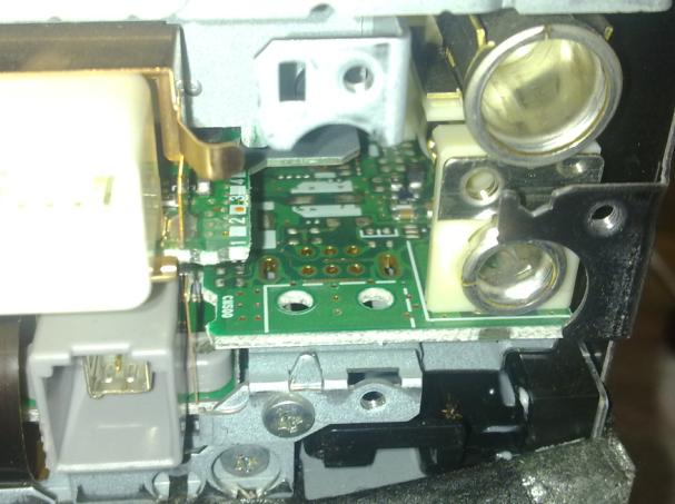
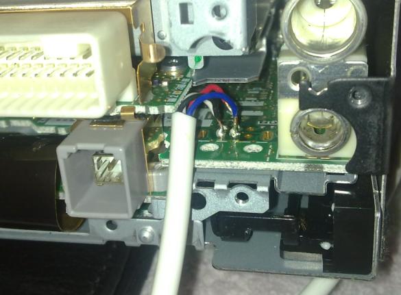
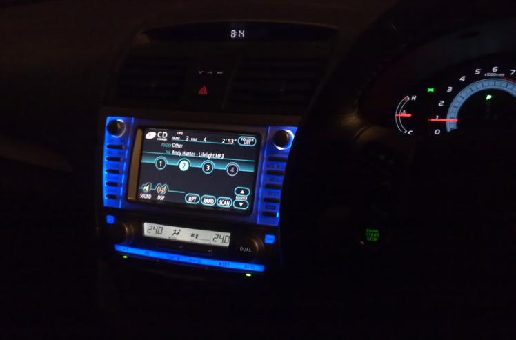
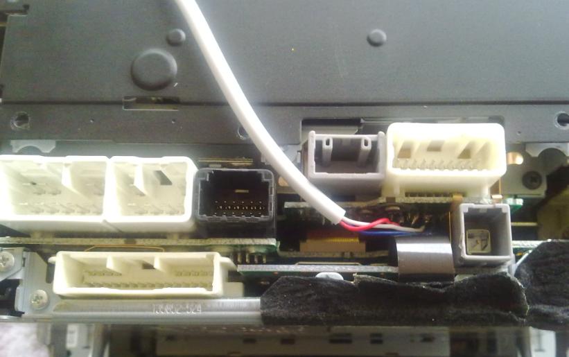
Haven't heard back from Fugitsu yet - even if I were, I think it's a little too early yet. Pictures included show the pads, where I've soldered on - how the wire looks hanging out the back... and a little something I changed just to make it feel my time. Now to make the rest of everything match it, but that's for another thread.

-
okay guys, good news and bad news. The good news is that I found the PCB connectors for the missing 6 pin plug - exactly where they should be. I was even able to solder wires to the PCB pads, and all test okay with a multimeter. The bad news, still no AUX. It might have been disabled inside the units firmware is my only guess at this point. I took plenty of pics, and will upload them after I've got everything back together - as a means to try and get better access to the PCB I disassembled a fair bit of the unit - only to find that the access I needed would probably be the last thing I would get, hence I just soldered it through the small hole I had. It worked, kinda.
-
That's a good question - depending on what the answer is from Fujitsu Ten, I might pull the unit out again this weekend and have a look for that.
-
Unfortunately there's only a blank area there without plugs. There is a grey plug as shown in the above picture, that only has a single grey wire running to it - I'm not sure of the purpose of this plug - in all diagrams I've seen sofar it hasn't been labelled (but is included in the pictures). I've sent an email off to fugitsu ten requesting a pinout diagram, here's hoping they might actually give me one...
-
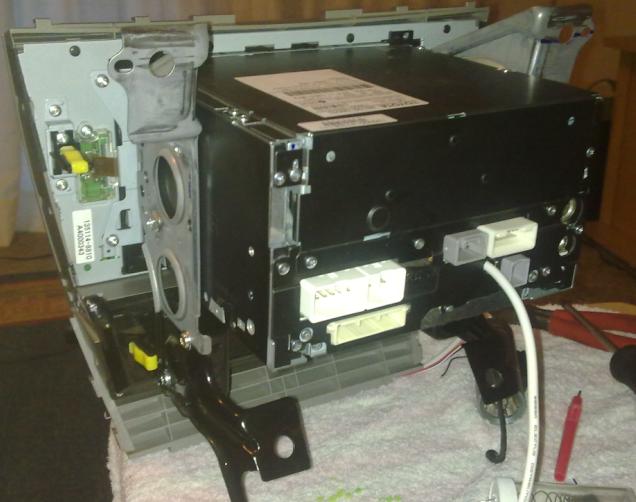
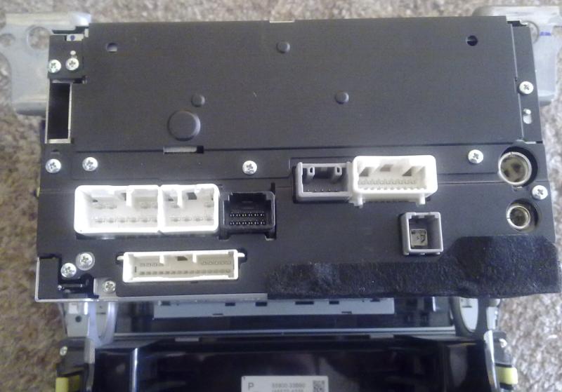
Steven, I though shane_85 said in Post #4 to use the following connections if you have a factory Sat-Nav unit: So im ASSUMING (i know its bad to assume but it paid off for me!) from the manual you will be looking at F14-6(ADPG) to F9-20(GND) - enable the AUX ....through 1K resistor that is F14-2(VAR+) - Right Signal, F14-3(VAL+) - Left Signal & F14-5(VA-) - Signal Ground/Shield Are you able to locate the F14 connector on the back of the factory Sat-Nav? I too have a factory Sat-Nav and I am going to do this mod in the next few days.... I guess I should wait to see which connector I should be using before ripping out the factory Sat-Nav... Yeah there isn't any F14 plug. You should be able to compare the pictures I've posted of the back of the unit to that in the manual.
-
Has anyone with the factory SatNav unit got this working? The back of my unit doesn't 100% match up with any unit shown in those linked PDF manuals, and I believe that might be why it's not working for me.
-
Well no luck. Final test with multimeter shows wires are exactly where they should be, and don't short against anything either (nor each other). Using both kinds of resistors grounded to the headunit cage (which multimeter shows to have virtually no resistance between itself a a metal part of the car, hence a good ground) I cannot get any AUX mode to show up by pressing either the Mode button on the steering wheel, or the CD button on the unit itself.
-
Knowing me, it's probably just not getting a good connection - hence I just soldered it directly to where the plug attaches to the PCB. Not much space, but all done and the good ol multi-meter shows no shorts between soldering. I'll be trying everything from a 0.100 kohm resistor to a 0.9kohm resistor. they're all I have around.
-
Counting the pins is a good start if you are having difficulty. Anyways to make it easy for you, here is what you should be looking at: That's the plug I was currently experimenting with - however grounding F8-19 through a resistor has not given me the AUX option when cycling through MODE on the steering wheel...
-
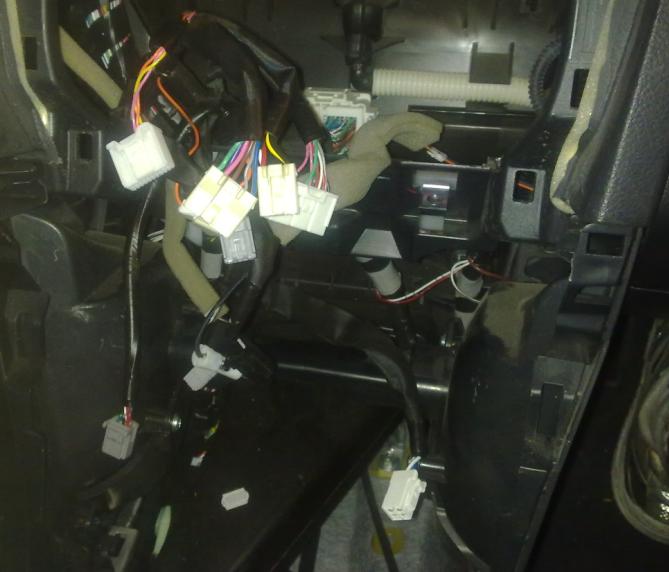
Which plug did you use? Looking through those manuals, as well as my own unit, I'm unable to find the corrosponding plug behind the satnav unit (pictures included) Anyone able to point me in the right direction here?
-
Only for the first 60k. After that, you have around 40k in which you'll have to fork out the full amount by yourself.
-
Many car audio headunits with screens use a CCFL tubing to backlight their screens - designed for car use including vibration and heat they don't normally fail despite constant use. So as said, properly designed tubes and inverters should be up to the task. Despite this though, CCFL tubes do have a very limited lifespan compared to LEDs, and are also not as efficient.
-
I don't think they can forfeit any warranty if you choose a different mechanic to service your vehicle (provided he's a licensed mechanic of course)
-
How much can the stock "basic" head unit push?
Steven replied to TheMirror's topic in Aurion / TRD Aurion Club
I think you're getting confused between Max values, and RMS values, in regards to output. The 4 x 35w is the max value of that amplifier, same as how aftermarket units claim 4 x 50w are also max values. Looking through the data sheet, I see the actual realworld output is only around 17w RMS - which makes sense as aftermarket units claiming 4x50w usually put out around 22-25wrms per channel. It still strikes me as pure advertising BS when companies still advertise Max values when selling their products - you will see that all the companies that sell high end gear to customers who know their stuff, will only quote in RMS values (real world output) Still thanks for the input and effort, now we know exactly how much you stand to gain even just by installing a basic 4x50wrms amp (cheap as chips these days) -
If you are going to run an amp, you can expand your search to perhaps include some lower efficient speakers - considering power won't be an issue. Also a decent component set of speakers is worth considering as well, especially if an amp will be thrown in the mix - generally they tend to have a smaller mounting depth than 6x9s anyway.
-
How much can the stock "basic" head unit push?
Steven replied to TheMirror's topic in Aurion / TRD Aurion Club
do you really think the standard headunit would put out anymore than 25w RMS? I'd figure that 25w would be the best case scenario for a factory amplifier, it's on the higher end even with aftermarket headunits. Based on how lightweight and efficient the factory speakers are, I would guesstimate the factory output to be around 15-20w RMS. Whether the aftermarket 6x9s will give better bass will depend heavily on how they're installed (as mentioned), and how efficient that are compared to the factory speakers. -
I actually had something exactly like this happen in my last car, a 97 Commodore sedan, whilst on the freeway. The steering wheel started shaking so bad I thought the front wheels were going to fall over, and it happened quite suddenly too. My response was also the same as yours. Over the next month I had every component of the front steering and suspension looked at, not to mention having the wheels balanced more times than I can count as well as several alignments. In the end, it never did happen again but the original source was never discovered, I've since been led to believe that yes it's just one of those rare fluke occasions where any number of factors combine to cause a temporary condition. Recommend checking your bearings and steering rack - jack front wheels up, try moving the wheel back and forward from both the top/bottom (bearings) or from side/side (rack ends). There should be close to no movement at all, if so get the relevant part checked out and don't drive the vehicle. Otherwise, keep a close eye on it, if it's once off naturally it's unlikely it'll happen again
-
done a fair bit of research, and I think I'll use 10uf capacitors and a 0.3Mh Inductor to get a crossover around 3khz on a 12db/octave slope. Should get a much better overall response. I'm using mini XT-25 tweeters, and even using the factory capacitor they sound great. Modified them to be as factory fit as possible, all that's left is to create a mounting bracket and they're done.
-
Something must be amiss here I've removed the front tweeter assembly - the factory tweeter is roughly 4ohm. The capacitor in series with it, is rated at 25v 3.3uf Now unless my figuring is completely wrong, this puts the factory Hi-pass filter at around 12000hz! Here I thought that large style tweeter, looking more like a midrange, would be around 1000hz - this would explain why the factory stereo sounds "warm" but not very detailed, instead it's the opposite. Is my figuring wrong peoples?
-
does anyone know what the standard high pass filter on the dash tweeter is set to? Looking just to do a drop in replacement with something aftermarket, but they look like they'd play alot lower than regular tweeters (ie be half midrange)
-
looks good mate - very neat! I have some time off over christmas, might give it a go myself. I've got the sat nav unit, hopefully it's not too different
-
at that price for those ebay ones, I'd be tempted to get some just to prove how crappy they really are
-
commercially available and viable LEDs are improving, but are not yet near the capabilities of HID. You can get some very bright LEDs, but to come even close to HID you would need quite a few of them. Yes you could get some LEDs that would do that job, but be prepared to pay through the teeth for a very specialised set up. Also despite popular belief, they actually can run very hot too making a cooling arrangement necessary as well.